Yes must be an age thing, done the big amp and speakers thing and found you don't really need it.
Now I have finished the power cable I just pulled the rear speaker covers.
I'm going to fit some Alpine SPE-13C2 as they are cheap, very efficient as they are designed for head unit power only, shallow mounting depth and with a cutout requirement of 110mm vs the 115mm available in the car they should just fit. I will have to make up some custom alloy plate to mount them on however as the mounting point that pertrudes into the hole with have to go completely. Got about 25mm from the face of the existing speaker to the inside of the plastic trim so the tweeter should be fine as well.
Will fit the 6.5" JBL 3 ways in the front and forget about a A pillar mounted tweeter completely. The rears should fill the top end and if it doesn't I can just connect the factory front tweeters and bring them in as well. I presume the factory tweeters have the bipolar crossover capacitor already mounted on them.
Holy crap rear speakers are hard to replace
Moderator: Moderators
Forum rules
This area is dedicated to technical discussions concerning in-car electronics. Stereos, alarms, GPS etc. Please try to spell correctly because this will help people find information later if they are using search functionality. If you need assistance with your car and want to host a spanner day, please use the appropriate section of the forum: http://mr2.org.nz/phpbb3/viewforum.php?f=35 Thank you.
This area is dedicated to technical discussions concerning in-car electronics. Stereos, alarms, GPS etc. Please try to spell correctly because this will help people find information later if they are using search functionality. If you need assistance with your car and want to host a spanner day, please use the appropriate section of the forum: http://mr2.org.nz/phpbb3/viewforum.php?f=35 Thank you.
-
Tronic

- Guest of the Club.
- Posts: 1942
- Joined: Sun Feb 12, 2006 8:19 pm
- Prime Mover: More than one MR2
- First name: Carl
-
CJ

- Club Member - MR2OCNZ
- Posts: 1400
- Joined: Wed Aug 17, 2005 6:55 pm
- Stomping Ground: Waikato
- Prime Mover: SW20
- First name: CJ
you dont need a big amp. the head unit is a "source reader" Its not designed for powering the speakers. even the stock MR2 setup had this.
even a new 50x4 head unit will not drive clean power through your speakers.
ive seen countless people think they just cant seem to find decent speakers that dont blow after a while only to find out theyre just running them off the head unit.
you can get a perfectly good little 4 channel for around $100-$150.
-
CJ
- Club Member - MR2OCNZ
- Posts: 1400
- Joined: Wed Aug 17, 2005 6:55 pm
- Stomping Ground: Waikato
- Prime Mover: SW20
- First name: CJ
if you hook 50w speakers up to a 1000w amp then yes.
if you buy a small amp say 50x4 or 100x4 and some half decent speakers like the explods then they will last longer than on a head unit.
pushing a head unit thats rated at 50w constantly at 40w will push distorted power into your speakers, wrecking them.
if you have 100w from an amp going into your speakers at a nice listening level, the speakers receive nice clean power.
If you think about the physical size of a small amp, its bigger than a head unit. the head unit has a cd player, maybe a screen, tuner, equalizer all inside the one case. theres just no way you can fit a quality amp inside the small space, so they make them shit and tell you theyre capable of dishing out 50w per channel. what youve got to check is at what point does the little amp in them start distorting. it may start distorting at only 10w power.
If you get an OK brand amp it may not start distorting until say 90% peak.
A lot of cars now have a small amp built into them, like the MR2.
-
tw2

- Area Coordinator - MR2OCNZ
- Posts: 1349
- Joined: Wed Jun 24, 2009 9:32 am
- Stomping Ground: Waikato
- Prime Mover: SW20
- First name: Thomas
Interesting, I will consider this carefully. If I can hide a small amp somewhere I may go down that route. I decided on the fusion reactor components in the end, I am not sure if they require a dedicated amp, they are rated at 65rms not that I think I will ever be cranking them that much.
Thomas, 91 G, 05 E55
Area Coordinator Waikato
Area Coordinator Waikato
-
Tronic
- Guest of the Club.
- Posts: 1942
- Joined: Sun Feb 12, 2006 8:19 pm
- Prime Mover: More than one MR2
- First name: Carl
Yes its true low powered amps blow speakers, or typically the midrange speaker if there is one. At high volume the distortion, due to clipping of the waveform effectively produces high frequency harmonics that go to your midrange and tweeters. Unfortunatley due to the response of the human ear A. you tend not to hear the distortion until its pretty bad and B. You need massive amounts of power to keep the Audio waveform from not clipping at all with a CD source due to the dynamic range of CD.
50Wx4 is fine for background music and the average listening volumes that don't make your ears bleed.
Ideally every individual speaker should have its own amp and the amp would be supplied via an active crossover. Bass speakers need a whole lot more power and the mids and tweeters need a much smaller amp. This is the ideal set-up however it is both expensive and harder to set-up and tune.
Not sure about the factory amps in the MR2 but they are most likly just the typical bridged amps that you find in the head units these days. Back in the day they were quoted as 20W a channel as the MR2 came out the same time I was an audio technician finishing my apprenticship.
Carl
Electronics Technician.
1990 Gen II GT Ceramic CT26 Hybrid @ 15psi
170.5 kW @ 6429 RPM 288.7 Nm @ 5430RPM
Gary Capper Performance - "Dynamic Test Systems" Precision Dynamometer
Electronics Technician.
1990 Gen II GT Ceramic CT26 Hybrid @ 15psi
170.5 kW @ 6429 RPM 288.7 Nm @ 5430RPM
Gary Capper Performance - "Dynamic Test Systems" Precision Dynamometer
-
tw2
- Area Coordinator - MR2OCNZ
- Posts: 1349
- Joined: Wed Jun 24, 2009 9:32 am
- Stomping Ground: Waikato
- Prime Mover: SW20
- First name: Thomas
Listened to my system for 50 minutes today (driving obviously) and the rears really do make a whole lot of difference. I could be tempted to leave the fronts except there is just a little bit of bass missing in some songs which I think will improve with the 5.25's. Not sure how to cram a 50mm tweeter into the sail panel....
Thomas, 91 G, 05 E55
Area Coordinator Waikato
Area Coordinator Waikato
-
vvega
- Guest of the Club.
- Posts: 892
- Joined: Fri Sep 24, 2004 12:04 pm
http://www.monstercable.com/mpc/stable/ ... _Facts.pdf.Copyright 2000 by Autosound 2000, Inc. All rights reserved, no part of this publication my becopied, reproduced, or stored by any means, electronic, mechanical, optical, or otherwise withoutwritten permission of Autosound 2000, Inc. A2420 SOME FACTS ABOUT DISTORTION AND SPEAKER DAMAGE By Richard ClarkThe subject of speaker damage is always a high interest topic in car audio circles. Because many of ustend to run our speakers close to the edge, the possibility of damage is greatly increased. A goodunderstanding of why speakers actually fail can be of great benefit to designers, installers and operatorsof audio systems. It is unfortunate that there is so much misinformation about this subject. Becausecertain aspects of the subject are very complex, it is no wonder that there are so many explanationsfloating around.Some of the aspects of speaker damage are rather easy to understand. Mechanical failure due to certainphysical related factors is obvious. For instance, poking a hole through a cone with your foot doesn't takemuch of a study to evaluate. Wrecking a speaker because it moved so far that it literally ripped itssuspension and cone apart is also a common mode of failure. Many woofers that are used in poorlydesigned boxes have met this fate. Tweeters without adequate crossovers have also seen a lot of failuresdue to over-excursion.Thermal FailureAlthough for this article we don't intend to cover such obvious modes of failure, there is one that we wantto cover. This is known as thermal failure. As the word implies this failure is a result of the temperature ofthe speaker getting too hot. It would seem that the cause of this should also be obvious, however, aftertalking to many consumers, subscribers and manufacturers, it seems that this failure is not clearlyunderstood.After hearing some of the explanations for the actual causes, I am no longer surprised that it is socommon. It seems that there are a lot of technically unfounded theories as to the cause. We felt it wastime to clear up some of these myths!When we say that a speaker "burned up" we are usually referring to the fact that something in thespeaker actually got so hot that it burned up. Just like any other object that burns as a result of getting toohot, certain components in a speaker will actually burn up rendering the speaker useless. These parts areusually the voice coil and the former that it is wound on. Too much electric current flowing through the coilcauses the heat. Just as with a hair dryer element or light bulb that glows when current flows through it,the voice coil of a speaker will also get excessively hot if the current exceeds a certain amount. Thisamount is determined by several factors. The size of the wire can matter. The larger the wire the morecurrent it can handle. The type of insulation on the wire can have a big effect. Some types of insulationare more temperature resistant than others.Even the shape of the wire can matter. Certain shapes such as flat ribbons can allow more exposure tocooling surfaces. The former that the coil is wound on can be made from anything ranging from paper tometal and can greatly influence thermal limits. The type of glue used to hold the parts together can havedifferent resistance to temperature. Some of the more modern epoxies have the remarkable ability towithstand high temperature.Regardless of how the speaker is made, there is always a limit to the power it can safely handle withoutdamage. It is usually in defining this power limit that we have a lot of confusion. When we rate anelectrical device we use the term watts. Some electrical devices are easy to rate. Take for example a lightbulb. When we rate a light bulb at 60 watts, we know that 60 watts of power will flow continuously throughthat bulb as long as it is turned on. If we increase the power by a significant amount, the bulb will burn upbecause its filament will get too hot and melt. If, we reduce the voltage to the bulb then the filament will
Page 2
cool off and the light will become dim. As long as the voltage and current remain within the designparameters of the bulb, it will work as intended. With a constant source of power it is easy to rate thepower capacity of a component.Speaker Power RatingIf we were to rate a speaker the way we do a light bulb, it would be easy to arrive at a value but thatnumber would be useless considering the way we use our speakers. Unlike AC line voltage, musicsignals are constantly changing. If we look at a typical music signal over a short period of time we will seethat there are peaks that are several times as large as the average level. When we consider the power ofsuch a complex signal, the actual values of the waveform must be integrated over a given time period. Itis the total power under the curve that determines the power, therefore the heating, of the signal.For an example of this examine the following charts. The measurements were taken from the speakerterminals of a power amplifier. Each chart is a display of power for a period of one minute so each verticaldivision represents 15 seconds.Figure 1 shows a constant power level of a 1 kHz sine wave. For the entire one-minute measurementperiod the level shows no variation. This continuous signal is similar to the 60 Hz that a light bulb wouldsee. Figure 2 shows the levels that are typical of music. The levels can be seen to vary over a range ofabout 20 dB. The interesting fact about Figures 1 and 2 is that when the music is averaged over theperiod of one minute, it represents exactly the same power level as the continuous sine wave. Thehighest power point in the music selection is near the start of the song and is nearly 10 dB louder than theaverage level. This high point is in contrast to the lowest point that occurs about 20 seconds into thesong. The lowest point is about one tenth the average power (about 5 watts).If the continuous sine wave of Figure 1 were used as a reference and played at a power level of 50 watts,it is easy to see the heating effect that would occur in the voice coil of a speaker. What is not alwaysunderstood is that if the signal of Figure 2 were played into that same speaker, the heating effect wouldbe the same even though there were momentary peaks of 500 watts. If our speaker were rated at a trulyhonest 50 watts continuous, neither of these signals would cause any thermal damage even though themusic had peaks that reached 500 watts. It may cause excursion damage but that is another failuremode.Thermal MassBecause the duration of those 500-watt peaks was very short, the voice coil would not have time toactually heat up. To understand why such large power peaks do not damage the coil we have to think ofthe term thermal mass. Even though the power is high the coil can absorb a certain amount of heatbefore its temperature starts to rise to unsafe limits. This principal is easily demonstrated with a candle. Itis easy and painless to pass a finger through the flame of a candle as long as it is done quickly. Thisdoesn't mean the candle isn't hot. It just shows that the thermal mass of our finger is able to absorb acertain amount of heat before we start to get burned. As long as we give our finger time to cool betweenpasses we can do this repeatedly.Now for an extreme example of power variation. Figure 3 is a power vs. time plot of a snare drum beatreproduced by a very large amplifier. The average power of this signal was also the same as the signalsin Figures 1 and 2. Some of the beats are 17 dB louder than the average level. Seventeen dB above 50watts is over 2000 watts! If our 50-watt speaker were driven with this signal, it is very likely that it wouldnot be damaged due to the cooling period between the peaks. Even though the momentary peaks arevery high, the average power level, and therefore the average heating effect, is only 50 watts.It is this very nature of music that makes rating the power of speakers so difficult. If our sample speakercould handle 50 continuous watts, we could rate it at that power level. If we were going to play only toneswith our system then it would be simple to properly match it to a 50-watt amplifier. If we were going to
Page 3
play music with our system, a quick look at Figure 2 will show us that a 50-watt amplifier would probablynot be adequate for our speaker.The speaker was easily able to handle 500-watt music peaks. If the speaker were matched to a 50-wattamplifier and we tried to play the music of Figure 2 at an average power level of 50 watts, we would findthat the amplifier would be greatly undersized for our 50-watt speaker. In such a case we would find thatthe amplifier would be very distorted during most of the music. Anytime the signals consisted of peaksthat exceeded 50 watts, they would be clipped by the amplifier.DistortionThis brings us to an interesting, but often misunderstood, subject. ---- Distortion. Let's consider the factthat all music is composed of sine waves. The combinations of frequencies, amplitudes, and phaserelationships are virtually infinite. To keep the explanation simple, let's first consider a single sine wave.Most amplifiers have no trouble passing a sine wave with virtually no distortion. They can do this at alllevels up to their maximum rating. The power supply rails usually determine the maximum rating. Therails of an amplifier are the outputs of the power supply of the amplifier and are a DC potential. In modernamplifiers there is usually a positive and negative rail. When the amp is outputting a sine wave, theenergy is diverted from these rails by the output transistors that act as variable valves.As the sine wave swings positive, the energy is diverted from the positive rail and when it goes negative,the energy comes from the negative rail. As long as the voltage required for the sine wave is less than thepower supply rail, the amplifier will have no trouble reproducing the signal without distortion. When thesignal required is higher than the rail voltage, then the transistor acting as a variable valve is turned oncompletely and the rail of the amplifier is literally connected to the speaker. This full "on" condition isknown as saturation and it occurs for whatever duration of the wave that exceeds the rail of the amp. SeeFigure 4 for a simplified block diagram of an amplifier and the relative relationship of signals to railvoltages.Amplifier ClippingThis saturation condition is more commonly referred to by the name that describes what it does to thesignal. We call it "clipping." Perhaps no other facet of amplifier behavior is more misunderstood than thiscondition. Let's cover some of the myths. First it is commonly believed that clipping is bad for an amp.Nothing could be farther from the truth. The transistors in an amplifier operate in a linear mode. Thismeans that for a given current, the power dissipated by the transistor is proportional to the voltagedropped across its junction. When the amp is clipping the transistors are fully saturated and have virtuallyno excessive drop across their junctions. This places them in their most efficient condition. True digitalamplifiers operate in this condition all the time and this is why they are so efficient.Pure DC?It is also commonly believed that when an amplifier clips that it puts out DC. A quick look may make thisappear to be true, but it would have to be a very quick look. Let's take the example of a clipped 100 Hzsine wave. If we examine it for more than 1/200'" of a second, we will see that the signal inverts polarity atthe same periodic rate as an unclipped sine wave of the same frequency.The waveform we are describing is known as a square wave. But wait a minute here; a square wave isnot the same as DC. A pure square wave is a complex AC signal that is composed of a fundamentalfrequency and an infinite number of harmonics. Figure 5 shows an oscilloscope photo of a good squarewave. If we examine the makeup of this waveform, we will find that it is composed of many individual sinewaves. The first of these is the fundamental. We can observe the fundamental frequency by passing oursquare wave through a very steep low pass filter. This will remove all of the harmonics and leave only thefundamental. The fundamental is a pure sine wave of the same frequency as that of the square wave andcan be seen in Figure 6.
Page 4
If we move our filter up to three times the fundamental frequency, then we can observe the next harmonicalong with the fundamental. This would be known as the third harmonic and can be seen in Figure 7.Moving the filter even higher will reveal more harmonics.Figure 8 shows the fundamental with the third and fifth harmonics. By the time we add the fifth harmonicthe signal starts to resemble the familiar square wave. If we continue to add harmonics, the wave willeventually become more and more filled until it becomes almost square. If you still think clipping is DCand all this seems a little too confusing, we have a little experiment you can try that will convince you thata clipping amplifier doesn't put out DC.An Experiment into DistortionAll it should take to clear up the DC question is to put a large stiffening cap in series with a speaker. Thenhook your speaker to your car battery. No DC will flow because DC doesn't flow through a cap. Now hookthe speaker to your amp with the cap in series and turn up your amp until it starts to clip. The clippedsignal will go right through the cap. We all know that caps don't pass DC, right? So now that we are onthe right track let's get back to the facts. When an amplifier clips a signal, it causes the generation ofharmonics. These harmonics are also known by another name. This is what we call distortion. The morean amplifier is over-driven, the more the signal is clipped and the more distortion is generated. No matterhow much an amplifier is clipped, it will never produce a perfect square wave because the generation of apure square wave requires infinite bandwidth. In fact perfect square waves only exist in theory becausethere is no circuit with the bandwidth necessary to pass one -however, for all practical purposes some ofthem come pretty close.For the interests relating to loudspeaker power capacity, it is only necessary that we concern ourselveswith the very basics of square waves. We have already seen the frequency content of a square wave.When a square wave is compared to a sine wave of the same peak amplitude, the square wave will havetwice the energy of the sine wave. This is because there is more area under the curve but not all of thatextra energy is from the harmonics. If we examine the actual power contained in the individualfrequencies that make up the square wave we can see this more clearly.Figure 9 shows the relative power content of a square wave. The power levels relative to the fundamentaldecrease with each ascending harmonic. If we add the total energy of the fundamental sine wave with theharmonics we will get a total of 100% of the energy. What is important when we are considering theheating effect on a speaker is that the fundamental frequency of a square wave, which is a sine wave, willcontain 2 dB more energy than a sine wave with the same peak voltage as the square wave. Put anotherway, the fundamental of a square wave has a higher peak (27% more voltage, 62% more power) than thesquare wave itself.More Power?Analysis of this subject can get rather complex but what it really boils down to is that almost any amplifiercan produce twice its undistorted output if it is allowed to clip excessively. This extra energy results inabout 2 dB more energy at the fundamental and one dB in harmonic content.It also is commonly believed that there is a difference between square waves that are recorded inprogram material (such as might be found in heavy metal music) and square waves that occur as a resultof amplifier clipping. This is simply not true at all and an understanding of just what makes a square waveshould make this clear. By the time we have reached the third overtone (also called the 7" harmonic) thepower level is diminished to only a couple of percent of the fundamental. A whopping 81 % of the totalpower is still contained in the fundamental.If we are concerned about power dissipation in speakers it is easy to see that we need not concernourselves with harmonics much beyond this point. How the signal is generated is not important at all. Theonly thing that matters are how much energy the waveform contains. This is the only factor thatdetermines the heating effect on the voice coil of a speaker. It has been suggested that clipping can
Page 5
destroy tweeters. This is seldom the case. If only 19% of the energy is contained in the upper harmonics,then this doesn't really leave us with much destructive energy.Take the example of the case of a passive three-way system with crossover points at 100 Hz and 2000Hz. Suppose we clipped a 50 Hz signal going to the woofer with a 100-watt amp. We know that the ampcan produce 200 watts of square wave power. Looking at Figure 9 we can calculate that we would have162 watts (undistorted) of 50 Hz, 18 watts of 150 Hz, 7 watts of 250 Hz, 3 watts of 350 Hz, and 2 watts of450 Hz. By the time we reached the frequency range of the tweeter, the power would be fractions of awatt. If our system had a tweeter with a power rating of only 10 watts, it is unlikely that adding anotherfraction of a watt would make much difference.These harmonic levels represent the absolute worst-case conditions for a single frequency and do notaccount for the fact that program material contains complex frequencies, all of which clip simultaneously ifthe amp is overloaded. But the amount of overdrive needed to clip an amplifier to the level demonstratedis well in excess of 30 dB. For an amplifier with an input sensitivity of 2 volts, this would require an inputvoltage to the amplifier of over 50 volts! This type of drive voltage is virtually unavailable in car audioproducts.Of course the same effect could be achieved by feeding the signal to the amplifier in an already clippedstate, something that happens frequently. At any rate these excessive conditions don't really apply hereas the dynamic changes in music make it very difficult to continuously clip a signal to such an extremestate. Even when an amplifier is overdriven by as much as 20 dB (10 times the rated input voltage),clipping of the waveform will occur only for about 40% of the total time on music. At this point the music isso distorted that it is virtually unlistenable, at least for most listeners.For a demonstration of the actual spectral difference between normal program material and terriblyclipped material see Figures 10 and 11. Although the spectrum would be different for different types ofmusic these two curves should be comparable as they were the same piece of music.Figure 10 is the spectral content of a song averaged over a period of 40 seconds with 243 samples each.Figure 11 is the same song but it is massively clipped. The level was reduced so the curves wouldrepresent the same overall level. Notice that the overall spectral content is very similar to the original.These tracks are from our new amplifier level setting CD#104 and are Tracks 31 and 35 respectively. Thetotal energy represented by both tracks is exactly the same and will produce virtually the same heatingeffect in the voice coil of a speaker. The speaker doesn't care if the music is distorted or not. To aspeaker it is all just a combination of sine waves. A speaker cannot tell the difference between noise,distortion, or music. It doesn't care what kind of music it is or any thing else about it except how muchenergy is contained in the signal.What Really MattersThe real problem for our speaker is that any amplifier can produce more than its rated power if it isallowed to distort and clipping is a sign that you have probably reached the point where you should turnthings down. To get a real picture of what the speaker sees compare Figures 12 and 13.These represent the power vs. time of a song with very steady energy. They are in stark contrast to thesong in Figure 2 at the beginning of our article. Figure 12 is the output of an amplifier driven right to theverge of clipping but not quite. The amplifier was a MTX 4160 that is capable of producing about 219watts (AM certified) per channel into 4 ohms. Even though the peak power to the speaker is over 200watts the average power is only about 20 watts.Figure 13 is the same song and the same amplifier, but the gain has been increased until the amp isclipping very severely. Notice that the dynamics (ratio between loud and quiet passages) have beencompressed and that the average power level has increased by about 15 dB. Now the average powerlevel is about 100 watts and the peak power is about 400 watts. This means that our speaker is gettingfive times the heating effect that it was receiving before we started clipping the amp.
Page 6
PreventionIt is sometimes claimed that a good way to prevent speaker damage is to use a larger amp. This is trueonly if you don't turn the larger amp up until you exceed the average power to the speaker. A larger ampwill allow for the larger transient peaks to be reproduced without damage to the speaker because the totalheating of those short peaks is minimal anyway. This will almost always result in a cleaner soundingsystem. But if you continue to increase the power to the speaker until the average power is excessive,then it doesn't matter if the signal is clean or distorted ---- the speaker will overheat and burn up. Usuallywhen this is done the speaker will begin to distort before the amplifier. If this happens this is a sure signthat you are feeding the speaker too much power.When considering speaker power ratings and amplifier size it should never be forgotten that althoughamplifiers are usually rated with continuous sine waves, speakers rarely are. When matching amplifiersand speaker power ratings you are literally comparing apples and oranges. This should not normally be aproblem as long as we remember how the ratings differ.The most efficient woofers rarely exceed even 2%. If we put 100 watts of power into a speaker, thismeans less than 2% of the power is turned into sound and over 98% of the power is turned into heat. Thenext time you need to be reminded of how much heat 100 watts is just grab a glowing 100-watt light bulb.And just think, not all of the energy if alight bulb is turned into heat, in fact they are more efficient thanmost speakers!If your speaker were fed 100 watts continuously it would have to dissipate this much heat from its coil.Not many speakers are really designed to handle 100-watt continuous sine waves, but when rated fordynamic music that is constantly changing (providing cooling periods), a speaker that can only handleperhaps 50 watts continuous sine waves can easily deal with the undistorted output of a 400-watt amp.That's because the average output of that 400-watt amp reproducing undistorted music is probably notover 50 watts.If you can keep things under control you will be safe with the 400-watt amp. The same speaker that canhandle 50 watts of continuous sine waves can probably deal with 100 watts of a totally distorted amp.In nearly all cases when we see power ratings on a speaker, the manufacturer has taken into accountthat you are going to be playing music on that speaker. That is why we see ratings on some smalltweeters as high as 100 or even 200 watts. This usually means that if the amp is about the same size andnot allowed to distort, then the average power will be about right.It is not that distortion hurts speakers; it is just that distortion is usually a sign that something is too loud.This is also why we can find examples of 300, 500, and even 1000-watt woofers. You can be sure theseare not ratings for continuous sine waves, continuous music maybe, but not sine waves. Next time youthink you have a 1000-watt woofer, think about the heat produced by your hair dryer and imagine thatmuch heat building up in a small box in the back of your car ---- better get a fire extinguisher!
Wayne Dalton
Knower of stuff and things
Knower of stuff and things
-
tw2
- Area Coordinator - MR2OCNZ
- Posts: 1349
- Joined: Wed Jun 24, 2009 9:32 am
- Stomping Ground: Waikato
- Prime Mover: SW20
- First name: Thomas
Re: Holy crap rear speakers are hard to replace
So I did it again, now 9 years later in another (green/blue whichever) N/A SW20 I have replaced the rear speakers. This time I got some JBL 2-way components on the recommendation of my local audio shop, nothing special as the mr2 noise environment is terrible in my opinion. Unfortunately I couldn't help myself so this time around I did it with some very difficult improvements which probably aren't worth it. First was using some dynamat xtreme around the speakers to eliminate any vibration to the sheet metal through the mounting points. The second was to use some foam baffles.
The dynamat is easy to work with on a flat surface with metal all around, not in the rear where half of it is open air. The adhesive side is a pain to work with. It should be a dream on the doors though. Baffles are named poorly but are these:
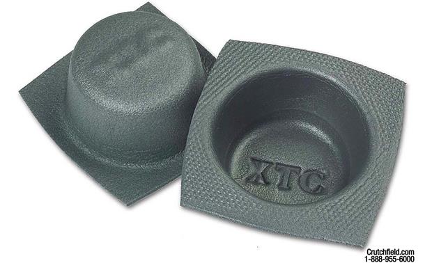
They are supposed to eliminate any dust and moisture getting into your speakers and also can create a closed airspace which is good for small speakers but will often cause bass reduction in larger speakers fighting against the small volume. People cut the bottom out for larger speakers. Just ram a screwdriver through to make a tiny hole for the speaker wires. There was plenty of dust all over the stock speakers so most likely this was not a bad addition. Of course both are next to impossible to install when you have only one small access point from the bottom and a seatbelt in the way. I was lazy and just cut a metal tab off the stock speaker mount to bridge the 4th hole in the top rear corner. I used the stock 10mm bolt for the bottom rear hole and the other two were drilled and bolted.
I had tried to order some PVC mr2 specific adapter plates from here http://www.car-speaker-adapters.com but they just took my money and nothing ever came, no communication so don't order from them ever. I got the full refund via paypal dispute though.
The dynamat is easy to work with on a flat surface with metal all around, not in the rear where half of it is open air. The adhesive side is a pain to work with. It should be a dream on the doors though. Baffles are named poorly but are these:
They are supposed to eliminate any dust and moisture getting into your speakers and also can create a closed airspace which is good for small speakers but will often cause bass reduction in larger speakers fighting against the small volume. People cut the bottom out for larger speakers. Just ram a screwdriver through to make a tiny hole for the speaker wires. There was plenty of dust all over the stock speakers so most likely this was not a bad addition. Of course both are next to impossible to install when you have only one small access point from the bottom and a seatbelt in the way. I was lazy and just cut a metal tab off the stock speaker mount to bridge the 4th hole in the top rear corner. I used the stock 10mm bolt for the bottom rear hole and the other two were drilled and bolted.
I had tried to order some PVC mr2 specific adapter plates from here http://www.car-speaker-adapters.com but they just took my money and nothing ever came, no communication so don't order from them ever. I got the full refund via paypal dispute though.
Thomas, 91 G, 05 E55
Area Coordinator Waikato
Area Coordinator Waikato
-
karenwillson
- Guest of the Club.
- Posts: 2
- Joined: Tue Jun 25, 2019 6:28 pm
- Stomping Ground: Wellington
- Prime Mover: ZZW30 (MRS / Spyder)
- First name: karen
Re: Holy crap rear speakers are hard to replace
t turns out the black window adhesive had melted into the deck fabric. It's NO exaggeration when I tell you I was pulling as if my life depended on it. I even have the scares to prove it!!! It was just insane. I dropped the seats, took off all the pillars, even the pieces next to the seat after I removed the seat sides, I even took down the piece covering the airbag!!! There was nothing even touching the deck and I pulled until I finally heard the sound of ripping along the back and sure enough the rear edge of the deck was saturated with the black butyl window glue. That is some TOUGH STUFF!!!!!!